LuiCat's Blog
Greetings.
4D Rendering: Projection & Cross Section May 23, 2018
In the Beginning
Thanks to all efforts I’ve made early days, I’m able to finish 4D rendering within moderate efforts. The final product gives a 4D-to-3D projection view and a 3D cross section view of each 4D objects, together with a data structure for 4D models and some 4D model presets.
Here is the WebGL version demo you can refer to: 4D Rendering: Demo
4D, How?
No, no, no. Don’t think about it too hard. The process is hard to imagine with a 3D image in one’s mind, but relatively easy if only looks at specific parts and join them with theories. Yes, I guarantee this will work. Mathematics is both for this. And don’t forgot your knowledge on Algebra.
Also better to read this post first for the knowledge of calculating 2D cross section of a 3D model: 2D Cross-Section in Unity
Some Basic Terms
Plane & Hyperplane
As imagined, there is planes in 4D space too. A 4D plane is determined by two non-parallel 4D vector. Amazingly, vectors that is perpendicular to this plane are not necessarily parallel. Actually, there could be two planes that only intersects at a single point (yes for most of the planes)!
Now think about this: Given a point and a vector, what could possibly be determined in 4D space? The answer is close to a plane, but hyperplane. With three non-determinant 4D vectors a 4D hyperplane is determined. On this hyperplane, everything are like what is in 3D space. Kind of like what we see on a paper, if we are saying 3D.
Projection & Cross Section
As we can only understand ordinary objects up to 3D by default, there are ways to help us to “see” 4D objects. Projection is one of the ways. All differences on the fourth dimension is offset according to a unit vector. The vector could be the direction of the camera, so it looks like all offsets on the fourth dimension are always forwards or backwards.
Cross Section is another way for us to understand a 4D object, kind of like cutting up an apple into halves. To be clarified, cross section doesn’t means to cut up with a plane, but to slice up at certain position on a direction, that is to cut up with a hyperplane.
Here It Goes Real
4D Rotation
First of all, to correctly show the cross-section at arbitrary directions of 4D models, or to extract value for a fourth dimension at arbitrary angle, we need at least a way to rotate models in 4D. To be clarified, there is no such imagined “rotation” but only axis switching in 4D; rotations happens on planes, and all points belongs to the same plane will still on the same plane after rotations along the plane; no exact “axis” can be determined for this operation.
After all these blablas, how about having a rotation matrix? What if we want to rotate from X axis to Y axis by θ degrees? We have the 4x4 matrix already:
[ cosθ  sinθ  0  0 ]
[-sinθ  cosθ  0  0 ]
[ 0     0     1  0 ]
[ 0     0     0  1 ]
As we’ve already known, this is a 3D rotation matrix with Z axis as rotation axis. This makes effects too for 4D objects, and the only difference is there is no “rotation axis” for this.
Similar with Euler Angles in 3D space, at least 6 angles should be use to determine the rotation of a 4D space. However, to keep it simple, just as the roll angle of a 3D camera is often omitted, we can only use 3 of the angles: WX, WY and WZ rotations. These rotations will alter the fourth dimension W and split some information of this axis onto the 3D space. This is the purpose of only choosing these angles.
The matrix for WX rotation (rotates W axis towards X axis) can be:
[ cosθ  0  0 -sinθ ]
[ 0     1  0  0    ]
[ 0     0  1  0    ]
[ sinθ  0  0  cosθ ]
Here is a sketch of calculating the rotation matrix with only WX, WY and WZ rotations:
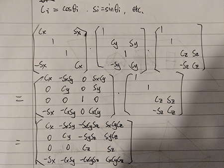
By applying it to 4D Vectors, rotation is done for sure. We can also extend the matrix to 5x5, but not really necessary. For the project, I only added an option of move the rotated model along W axis in order to see all possible cross sections.
To apply rotation universally to a model no matter what viewing method (projection / cross section) is used, I created a special getter function to prepare transformed vertices:
Vector4[] GetTransformedVertices()
{
    var vertices = (Vector4[])mesh4D.vertices.Clone();
    float cx = Mathf.Cos(modelRotation.x), sx = Mathf.Sin(modelRotation.x);
    float cy = Mathf.Cos(modelRotation.y), sy = Mathf.Sin(modelRotation.y);
    float cz = Mathf.Cos(modelRotation.z), sz = Mathf.Sin(modelRotation.z);
    var mat = new Matrix4x4(
        new Vector4( cx, -sx*sy, -sx*cy*sz, sx*cy*cz),
        new Vector4(  0,     cy,    -sy*sz,    sy*cz),
        new Vector4(  0,      0,        cz,       sz),
        new Vector4(-sx, -cx*sy, -cx*cy*sz, cx*cy*cz)
    );
    var offset = new Vector4(0, 0, 0, modelWOffset);
    for (int i = 0; i < vertices.Length; ++i)
        vertices[i] = mat * vertices[i] + offset;
    return vertices;
}
Projection
As concerned in another post (Designing 4D Model Data Structure for Rendering), there is some simple ways to project 4D models onto 3D space. However, these methods is simply created for testing, not uniform for different objects.
For this part, please refer to the section 3.3 Cross Section Algorithm in 4D of chapter Implementation & Results in my project report below. It’s really frustrating to write about the same thing twice. I’m lazy. Won’t rewrite it at present.