LuiCat's Blog
Greetings.
2D Cross-Section in Unity May 19, 2018
In the beginning
This mini-project is for gaining better understand of higher-dimension clipping procedures by making a script of 2D clipping algorithm, which generates an outline of clipped area of a 3D object with a plane. All tests based on Unity’s standard assets.
Also to be clarified, I have been using the wrong term “clip” for cross-section when I wrote this post. Sorry if this is confusing.
Choice of input / output contents
Input
For this part, Unity’s native class Mesh is pretty handy for this job. Also we can put a single Mesh in a MeshFilter, so that the 3D model and 2D clipped result can be rendered simultaneously.
Output
As in 3D clipping (with 4D objects!) the result would only be faces, rather than a collection of volumes, so that the equivalent result of 2D clipping should also be an outline, which doesn’t involve polygon triangulation of the area. For this purpose, LineRenderer is the most convenient choice from all.
The algorithm
Idea
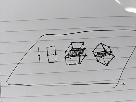
By simply drawing some sketches, it’s easy to find out that every clipped basic elements of a 3D object generates a responding lower dimensional element when clipped, e.g. a line generates a point, and a facet generates a line segment. Assuming every facets to be triangles, we would infer that every facet that is not on the clipping plane would have either 0 or 2 edges that clipped with the plane. With this property, we can calculate a graph of topology, in which two clipped edges that presents on the same facet is connected; then we simply draw the outline based on the graph.
Procedure
To begin with, we should determine which edges are clipped by the clipping plane, and which edges belongs to the same facets respectively. However before that, we need a important step as mesh from Unity’s standard assets doesn’t seems to have vertices at the same position fused…
0. Vertices Fusing
To fuse all close vertices together, which can be determined by Vector3.Equals, we use a look up table to see if there is already a vertex at specific position:
var mapVertexId = new Dictionary<Vector3, int>();
Then for every vertices from the mesh, we look up the previous entry of vertices if fusing is possible and fill out this array:
var vertexFused = new int[vertices.Length];
So that every time if we have to refer to a vertex, we refer to the vertex that appears first-in-order at the same position.
1. Classify Vertex Sides
For this part we calculate whether a vertex is on the positive or negative side of the plane based on normal vector. The side is determined by signature of dot product of normal vector of clipping plane and the position of the vertex to the center of clipping plane.
Also, all “fused” vertices can be omitted from calculation, as they are not used anymore.
2. Find Clipped Edges
With side information of vertices, we can determine whether an edge is clipped by clipping plane, that is, the two vertices of the edge on different side of clipping plane.
For every triangle facet, we know that there could be at maximum 2 edges that can be clipped by a plane at the same time, we record clipped edges in pairs:
// key & value for two pair of indices of edge vertices
var clippedEdgePairs = new List<KeyValuePair<Vector2Int, Vector2Int>>();
3. Generate Graph
For this task, we are going to fill out a adjacency list as the graph. To distinguish reversed edges (which the order of two vertices is reversed), we should also maintain a look-up table that maps both edges to a same symbol; a self-incremental id is recommended.
For each pair of edges from previous step, we look up the id numbers and create two opposite edges in the adjacency list for an undirected graph.
4. Calculate Intersection Points
Before we finally generate the outline, we have to determine the positions of all clipping points of edges.
For any edge that has a clipping point, the ratio of length of two clipped part of the edge is the same as the distance from the two vertices to the clipping plane. By projecting equivalent vectors to the normal vector of clipping plane, the ratio is determined, so that the clipping point is determined.
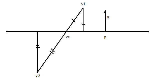
Calculation in C#:
// calculate the ratio of intersection point by measuring the ratio of equivalent vectors projected on plane's normal vector
float k = Vector3.Dot(planeCenter - v0, planeNormal) / Vector3.Dot(v1 - v0, planeNormal);
// then simply use the ratio to determine the exact intersection point
intersections[id] = v0 + (v1 - v0) * k;
5. Fill Out LineRenderer
Now we have to fill out the fields of component LineRenderer. As a continuous polyline is required, we won’t use any search method that expands all branches of the graph; an one-way search is enough.
Beginning from any node of the graph, we do a initial search so to find a node that is possibly the end of a longest path, just by visiting nodes that is not visited and neighbor to current node until there is not neighbor nodes. Do this search again from the last node visited in the first search, and use the list of visited nodes as result. The result will be good enough for most of the cases, and we don’t care about rare cases because they are not required to examine if all previous steps work right.
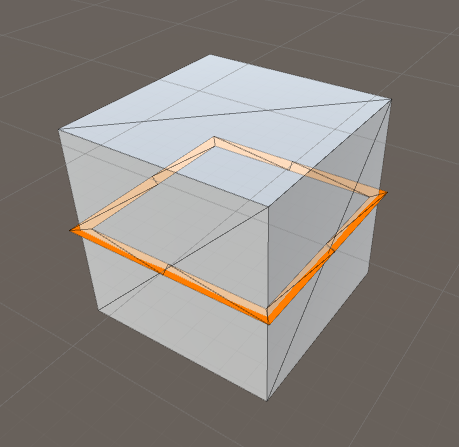
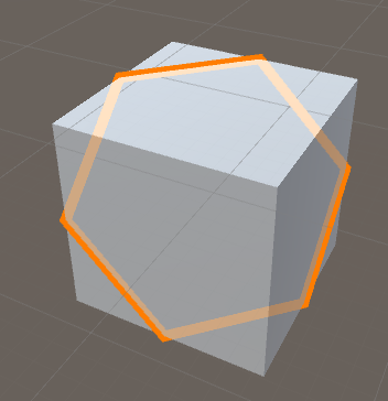
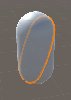
Results
Also…
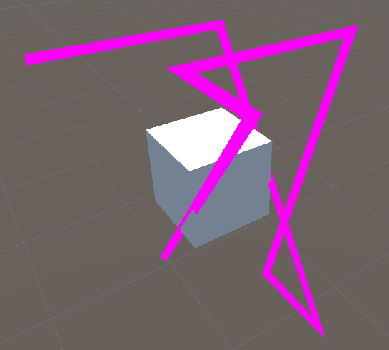
A bug introduced with incorrect ratios of clipped edges