LuiCat's Blog
Greetings.
Designing 4D Model Data Structure for Rendering May 21, 2018
My First Thoughts
From previous post 2D Cross-Section in Unity I thought about how cross-section (mentioned as clipping) works. As mentioned in the post, a cross-section applied to a 3D object basically converts every geometric elements into lower-dimensional equivalent element, e.g. a plane to a line, a line to a vertex.
For a higher-dimension space, i.e. a 4D space, a full-4D model should be consist of 4 basic elements excluding the model itself, which is relevant to 0~3 dimensional objects. As what usually a 3D model consists of, vertices and faces to be spoken out, to generate proper 3D model by cross-section, there should be proper data structure to note about the “3D faces” and edges. Luckily enough, the functions provided by Unity’s standard class Model has enough information for us about how a data structure for “3D faces” would consists of. The only problem is to use 4D vectors for vertices.
Designing & Implementation
After thinking, I decided to use these fields as the properties of Mesh4D class:
[CreateAssetMenu(fileName = "TestData", menuName = "4DRender/4D Mesh")]
public class Mesh4D : ScriptableObject {
    public Vector4[] vertices;
    public Vector3Int[] triangles;
    public int[][] cells;
}
In this implementation, all vertices are 4D vectors, but triangles is still with 3 vertices (for sure!). I kept a list of Vector3Int for list of triangles rather that a int array with length of 3 times of triangle count. Then all cells is specified with triangle indices that forms the cells, e.g. a 5-cell (for an easier description, it’s a 4D tetrahedron with 5 vertices, the fifth vertex connecting every vertices of a 3D tetrahedron) contains 5 cells, and a hypercube or 4-cube contains 8 cells for each direction of 4 axes.
Being aware that 2D arrays won’t be editable in Unity, I created a wrapper for an triangle index array:
[System.Serializable]
public class TriangleArray {
    public int[] triangles;
    public int this[int index] {
        get { return triangles[index]; }
        set { triangles[index] = value; }
    }
    // ...
}
Looks like it works well in the inspector:
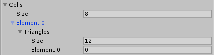
Also, utility functions are neat:
public int CellCount { get { return cells.Length; } }

public Vector3Int[] GetTrianglesByCell(int indexCell){
    var cell = cells[indexCell];
    var result = new Vector3Int[cell.Length];
    for (int i = 0; i < cell.Length; ++i)
        result[i] = triangles[cell[i]];
    return result;
}
Testing
Data Generation
I decided to implement generation for two 4D mesh assets: Pentachoron (5-Cell) and Hypercube (4-Cube).
Pentachoron (5-Cell)
A pentachoron, or formally a 5-cell, is a 4D object formed by 5 vertices in which every pair of vertices has the same distance in between.
For a easier setup, I put a tetrahedron in xyz-hyperplane and added a 5th vertex on top of the 4 vertices in w direction.
According to Wikipedia, the values for a 5-cell with edge length 2*sqrt(2), the vertices are:
( 1,  1,  1, -1/sqrt(5))
( 1, -1, -1, -1/sqrt(5))
(-1,  1, -1, -1/sqrt(5))
(-1, -1,  1, -1/sqrt(5))
( 0,  0,  0, sqrt(5)-1/sqrt(5))
For triangles and cells, I mapped all the indices within patterns according to this type of 2D projection of the 5-cell:
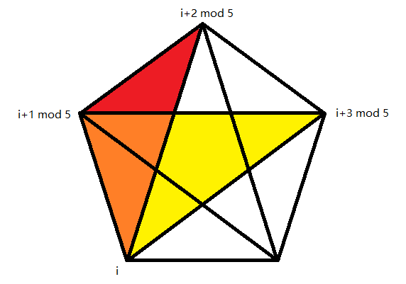
With this projection, I divided the triangles into 2 types:
Vertex indices of triangles #i
Side triangles   - (i, i+1 mod 5, i+2 mod 5)
Middle triangles - (i, i+1 mod 5, i+3 mod 5)
And also each cell contains 2 triangles of each kind:
Triangle indices of cell #i
Side triangles #i, #i+1 mod 5
Middle triangles #i, #i+2 mod 5
Then we are good to go!
Hypercube (4-Cube)
This one is much more complicated to keep track of all indices. It’s such a mess!
Take a look at my cheat sheet of all calculated indices, you will have ideas that how difficult it is to distribute indices manually:
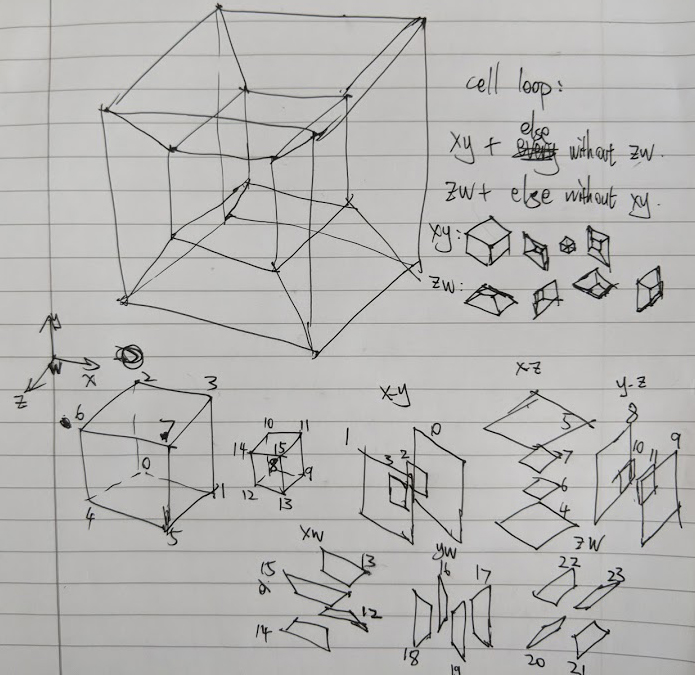
To actually determine the mapping between indices, I created a lot of lambda expressions for index mapping. Take one for example:
const int x = 1, y = 2, z = 4, w = 8; // constants for axis / dimensions
Func<int, int[]> rect2vert = (int rect) => {
    int[] dim; // dim = { dimMain1, dimMain2, dimSub1, dimSub2 }
    switch (rect / 4 % 6) {
        case 0: dim = new int[] { x, y, z, w }; break; // xy plane
        case 1: dim = new int[] { x, z, y, w }; break; // xz plane
        case 2: dim = new int[] { y, z, x, w }; break; // yz plane
        case 3: dim = new int[] { x, w, y, z }; break; // xw plane
        case 4: dim = new int[] { y, w, x, z }; break; // yw plane
        case 5: dim = new int[] { z, w, x, y }; break; // zw plane
        default: return null;
    }
    rect = rect % 4;
    int mainIndex = dim[2] * (rect & 1) + dim[3] * ((rect & 2) >> 1);
    return new int[] { mainIndex, mainIndex + dim[0], mainIndex + dim[1], mainIndex + dim[0] + dim[1] };
};
This function receives indices of 24 rect faces of a hypercube. The orientation, which is determined by the two main-dimensions, of the rects is changed every 4 indices, as there are exactly 4 rects with the same orientation. For each orientation, I also indicates which the other two sub-dimensions (that is vertical to the rect) are. By combining sub-indices, which is indices of rects with the same orientation from 0 to 3, with the two sub-dimensions, we got the indices of vertices that the rect is formed; by adding offset determined by two main dimensions, we got the exact four numbers of indices.
In response to rect2vert, there is a reversed function that converts main-dimensions and variables on sub-dimensions into indices of rects:
Func<int, int, int> dim2rect = (int dimsPlane, int dimsVar) => {
    switch (dimsPlane) {
        case x + y: return 0 + dim2idx(z, w, dimsVar); // xy plane
        case x + z: return 4 + dim2idx(y, w, dimsVar); // xz plane
        case y + z: return 8 + dim2idx(x, w, dimsVar); // yz plane
        case x + w: return 12 + dim2idx(y, z, dimsVar); // xw plane
        case y + w: return 16 + dim2idx(x, z, dimsVar); // yw plane
        case z + w: return 20 + dim2idx(x, y, dimsVar); // zw plane
    }
    return 0;
};
Func<int, int, int, int> dim2idx = (int dim1, int dim2, int dimsVar) => {
    return ((dim1 & dimsVar) == 0 ? 0 : 1) + ((dim2 & dimsVar) == 0 ? 0 : 2);
};
It’s clear that every possible orientations of the face is matched to a main-index (i.e. 0, 4, 8 … 20), and with parameter for the two other dimensions, the sub-indices is also determined.
With dim2rect, we can easy build up a 3D cell with 2D rects for the 4D hypercube. With the three dimensions that a cell lying on and the one parameter for the other dimension, the 6 rects is determined by switching out each of the three dimensions in order and also iterate the parameter for each switched out parameter. Also don’t forget that we need triangle indices here, so every rect index i is replicated as i * 2 and i * 2 + 1.
Func<int, int, int, int, int[]> dim2cell = (int dim1, int dim2, int dim3, int dimVar) => {
    return new int[12] {
        dim2rect(dim1 + dim2, dimVar) * 2, dim2rect(dim1 + dim2, dimVar) * 2 + 1, dim2rect(dim1 + dim2, dim3 + dimVar) * 2, dim2rect(dim1 + dim2, dim3 + dimVar) * 2 + 1,
        dim2rect(dim1 + dim3, dimVar) * 2, dim2rect(dim1 + dim3, dimVar) * 2 + 1, dim2rect(dim1 + dim3, dim2 + dimVar) * 2, dim2rect(dim1 + dim3, dim2 + dimVar) * 2 + 1,
        dim2rect(dim2 + dim3, dimVar) * 2, dim2rect(dim2 + dim3, dimVar) * 2 + 1, dim2rect(dim2 + dim3, dim1 + dimVar) * 2, dim2rect(dim2 + dim3, dim1 + dimVar) * 2 + 1,
    };
};

var cells = new Mesh4D.TriangleArray[8];
cells[0] = new Mesh4D.TriangleArray(dim2cell(x, y, z, 0)); // xyz0 cube
cells[1] = new Mesh4D.TriangleArray(dim2cell(x, y, z, w)); // xyz1 cube
cells[2] = new Mesh4D.TriangleArray(dim2cell(x, y, w, 0)); // xyw0 cube
// ...
Simply 4D-to-3D Projection
To have a simple view of 4D object and see if it’s valid, we should make some simple projection algorithm that “compresses” a 4D object into 3D space.
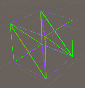
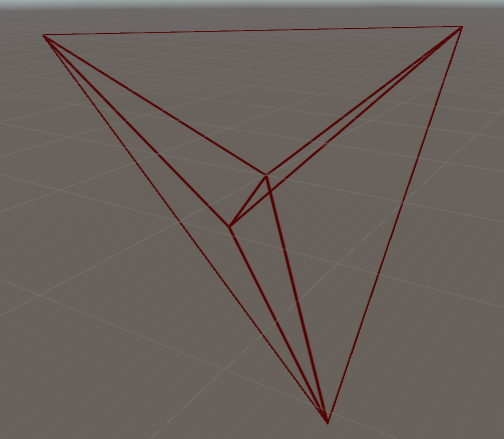
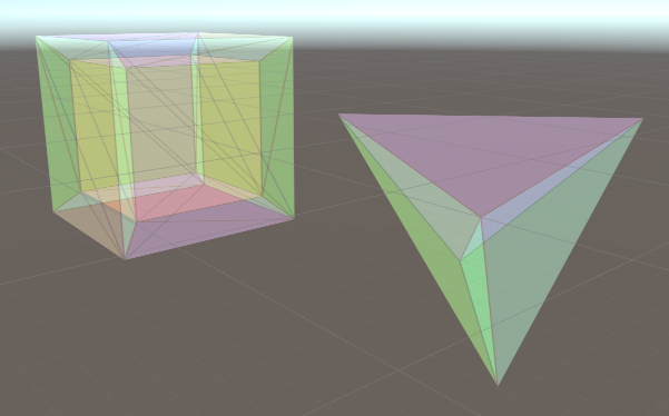
We can always ignore the 4th dimension and show all vertices with xyz info. With this method, an axis-aligned hypercube looks like a normal cube, and the 5-cell I’ve built above looks like a tetrahedron with a center vertex:
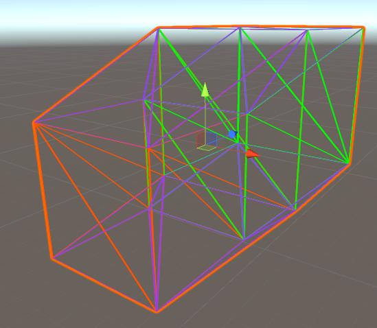
A alternative solution is orthographic projection, which in simple is to apply the distance on w dimension to a direction in 3D.
v3d = new Vector3(v4d.x, v4d.y, v4d.z) + Vector3.one * 0.57735f * v4d.w // 0.57735 == 1 / sqrt(3)
The equation above creates something like this:
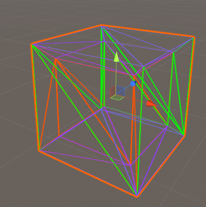
Another solution is perspective projection, which I did it in a special designed way:
v3d = new Vector3(v4d.x, v4d.y, v4d.z) * Mathf.Pow(1.35f, v4d.w)
I mapped w axis into some depth of view, but I used power instead of inverse so to match all possible w values to (0, +Inf). This would create a familiar view of a hypercube, which is called a tesseract:
I also altered some parameters of the shader that I am using, created a hypercube with more “volume-feeling”:
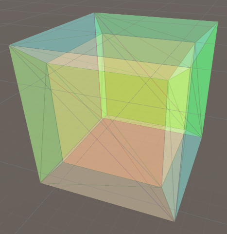
Another screenshot of both 4D mesh asset. Cheese!
References & Credits
- Unity Wireframe Shaders (https://github.com/Chaser324/unity-wireframe)
- Confusion of dimension terms: tesseract vs hypercube (Last revised 2004-01-16, http://hi.gher.space/classic/dimensionterms.htm)
- Wikipedia: 5-cell (https://en.wikipedia.org/wiki/5-cell)
Update History
- May 21, 2018 - Draft created
- May 22, 2018 - Finished